

After studying some other LM386 based 1/2watt guitar amplifier designs I noticed that where I had a 10KΩ resistor on the output, all other schematics have a 10Ω resistor there. I delved a bit further and found that the data sheet also specified the 10Ω resistor, so despite working – I was clearly mistaken.
I played around with some other component values, referencing the data sheet, and created a version of the circuit that cleaned up a lot of the distortion issues I had previously found with some of the LM386N-1 chips I have in stock. I mentioned these issues in my previous post of the power amplifier circuit which was nearly identical as it turns out to the ruby amp, essentially only omitting the volume control.
The following diagram diverges from the stock Ruby design on a few components based on my research and the data sheet information:
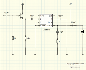
This version sounds much more passable as a clean power amp even with the chips that tended to distort more easily – I am eagerly awaiting the JRC386D 500mW chips I have on order to arrive, I anticipate it should sound very nice and loud now with those chips. The following circuit has been tested – you could easily add a volume control using a 10kΩ audio potentiometer between the 47nF capacitor and pin 2 of the IC and skip the whole preamp stage (pre amp not diagramed).
The J-FET transistor is an MPF102 and you will need power supply conditioning (not drawn above) – this is accomplished simply by putting a 100μF polarized capacitor between the +9V and ground rails. This is to eliminate noise from an AC adapter.
The circuit can be used with +5V to +12V, however I have only tested it with +9V and +12V.
For the rest of the design I currently have been testing it with an op amp buffer and two control tone stack, it has a basic effects loop breakout circuit which leads into the above amplifier circuit, hence the inclusion a J-FET buffer and no volume control in the power amp stage. All signal attenuation is done in the pre-amp stage after the op-amp and tone stack. I tried the volume control before the tone stack however I found that the passive tone circuit performed better with the full power of the buffer before it and the volume control reducing the signal after.

No Responses to “Miniature Guitar Amplifier – Power Amp Corrections and Cleanups”
Trackbacks/Pingbacks