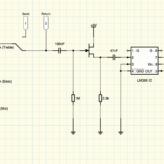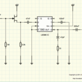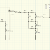
A few days ago I was lamenting, in a rambling sort of way, about being unable to get the distortion channel working on my test design. After redesigning and breadboarding the circuit many times I finally came across the core issue – I was configuring the op amp in a non-inverting format which was having unexpected results with the feedback loop. Once I realized my mistake I quickly whipped up a new version. Note that this is an...
Read MoreMiniature Guitar Amplifier – Never Expected to have THIS Problem
In my quest to figure everything out myself, instead of just blindly following pre-designed circuits, I’ve come up with a pretty good clean sounding 1/2 watt power amplifier as well as an effect loop and more recently a switching setup for dual channels using a DPDT switch and some nice tone shaping. For the most part, it’s been about 60% research and theory and 40% just trying things out and learning from the resultant epic...
Read MoreMiniature Guitar Amplifier – Tone Stack
The design is slowly starting to take shape for my guitar amplifier circuit. Here is the power amplifier stage with the simple effects loop and the tone stack portion of the pre amp that I will be testing next: This is essentially the same three knob tone stack found in most big name amplifiers. I’m still working on tweaking some values and have not yet wired this one up. Using the very useful Duncan Amps Tone Stack...
Read MoreSalt Water Etching
I always like finding new techniques for making and finishing projects, and this one looks to be a hugely beneficial process. Need to get a design onto metal with some permanence? Want to etch your own PCB board designs on copper clad boards? Look no further than the salt-water etching process. It’s so deceptively simple, it seems like it should be more difficult – but my tests have shown it’s really not. At it’s...
Read MoreMiniature Guitar Amplifier – Power Amp Corrections and Cleanups
After studying some other LM386 based 1/2watt guitar amplifier designs I noticed that where I had a 10KΩ resistor on the output, all other schematics have a 10Ω resistor there. I delved a bit further and found that the data sheet also specified the 10Ω resistor, so despite working – I was clearly mistaken. I played around with some other component values, referencing the data sheet, and created a version of the circuit that...
Read More