

After the success of the 3.1 prototype I took a break for a few months to let the concept stew. Several people have expressed interest in building one but the actual assembly process was quite complicated and over-engineered. Quite frankly, I actually didn’t put in all of the intended bolts because it was too tricky. There were other issues with the design such as the overall weight of moving mechanism which I have some ideas to address.
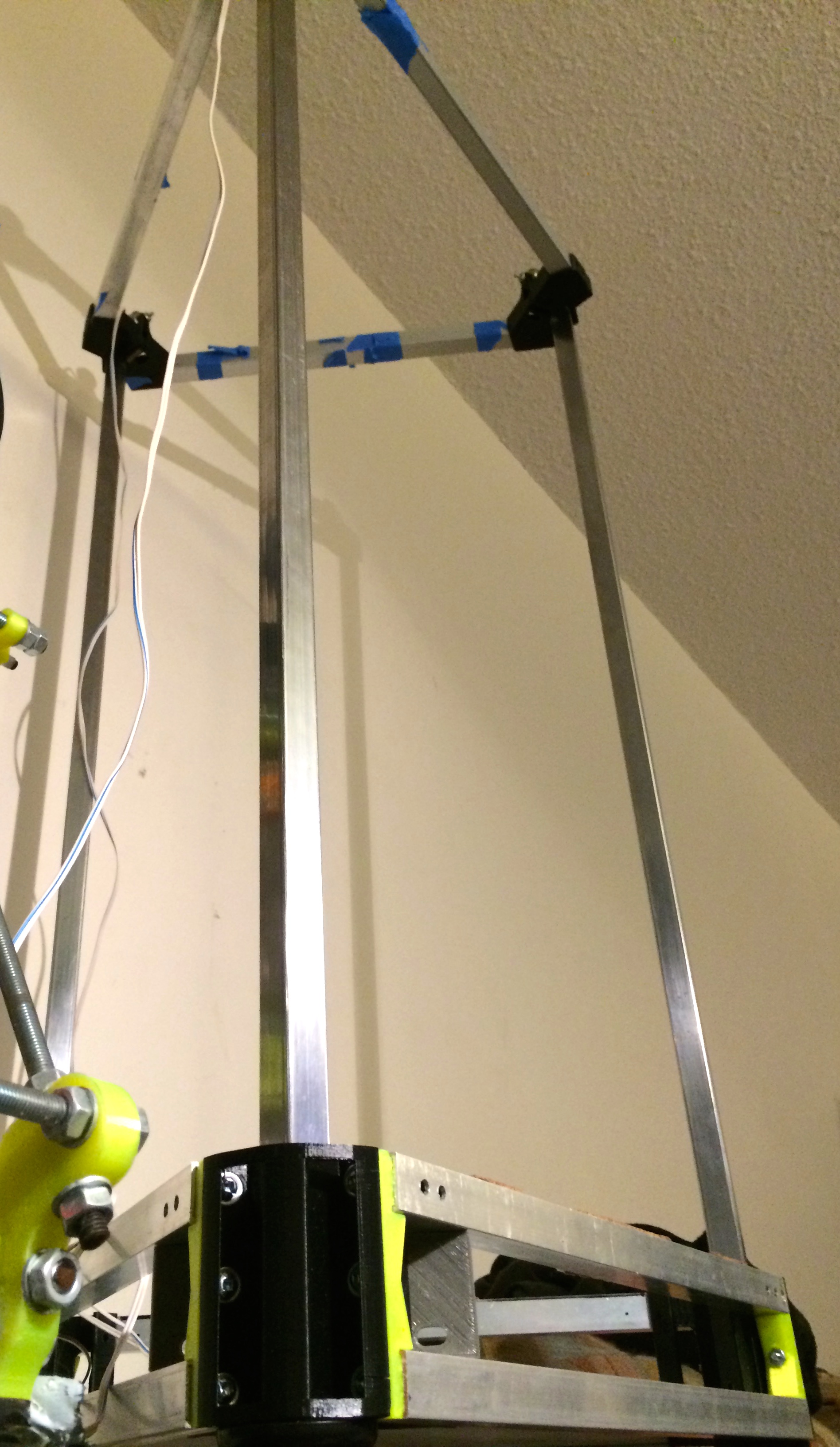
I came upon some inspiration for the frame issues recently and made some test parts which seemed promising. The above the photo is a test-fit mockup of the new machine – the vertical tubes are hand-polished 36″ tubes that are replacing the shorter ones from the first prototype. At the time of the first build I wasn’t certain the machine was gong to work so I used tubes I had onhand with the intent of purchasing new, longer ones, if it worked – which it did.
Here is a photo of the new bottom corner prototype I’m trying out:
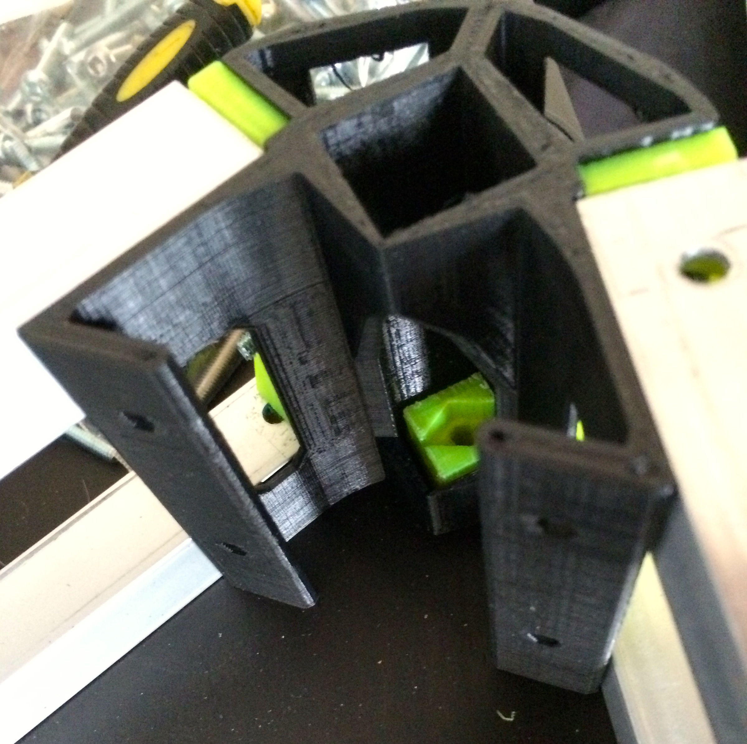
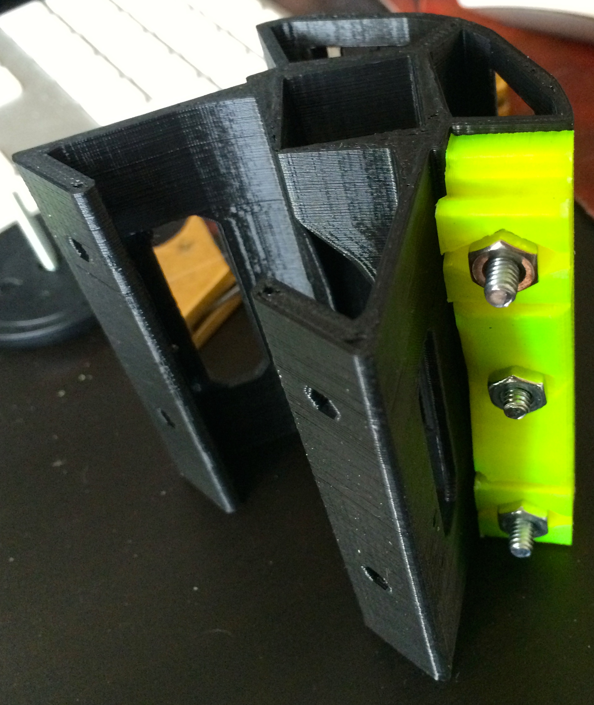
The essence is a large corner piece to which adapters are bolted to. The adapters have expansion plugs which slide into the tubes – these adapters, shown in yellow, necessitated being printed as separate pieces since they would have have produced overhangs that would have been unprintable were they to have been integrated into the corner piece. The central bolt holds the adapter in place while the expansion plugs are loose. This may not be actually necessary but it should make assembly a little easier.
The stepper motor mounts remain unchanged from the previous version. Not shown is an adapter plate that goes between the adjustable motor mount which will also bolt to the frame tubes. This is again a separate piece at a different orientation in order to accommodate the necessary overhangs. The adapter plate will be held to the corner piece by the motor mounting bolts and also to the frame tubes as I previously mentioned. It has a place to attach the floor and ceiling of the base unit (made of coroplast right now, but could easily be made of 4mm thick wood or perf board).
This is a test fit of the coroplast floor of the base, again without the aforementioned adapter plate (the plates are printing on my Mendel as I write this).

The cork strips are remnants from the first build where the 12″ x 12″ mirror tile rested.
Each corner has a large rubber foot that gets bolted in with the expansion plug going into the bottom of the vertical tubes to provide vibration dampening and a stable surface for the machine to rest on.
For every solution it seems another problem arrises – by plugging the bottom of the vertical tubes with an expansion plug I effectively blocked off the previous wire routing path. There needs to be a stepper motor, several fans, end-stop switches and the hotend wired at the top of the machine and running all of that wiring on the outside of the frame tubes is not an option on this machine. The frame tubes double as linear guides for the carriage bearings and having the wiring run up a separate channel on the outside of the printer ruins the clean look I’m aiming for. My plan so far has been to drill some holes in the tubing where it is exposed within the corners. To this end there are channels in the parts for running the wiring around the belt drive.
I think that I’ll need to disassemble the above pictured base and build each full machine corner before attaching the horizontal tubes. I need to do so in order to drill the mounting plate holes anyway. I should probably work out the proper top corner pieces and print them before taking the final assembly steps.
