

While researching and coming up with ideas to make a simple battery powered miniature guitar amplifier sometimes fanciness and elegance creeps into the conceptual stage. Here I will be rambling on about a few ideas and theories with which to complicate and elaborate on what is at its core, a very simple and effective design.
The amplifier I’ve built so far is very similar to The Noisy Cricket and is based off of the general theory involved. It’s well documented on his site, so it’s worth checking out.
I should note that the primary use of this amplifier is for testing DIY effects pedal circuits without risking damaging my good amplifier or causing my eardrums to bleed when something goes wrong and it all starts squealing!
Its low wattage output makes for safe testing and its low part count – while being built around a very cheap and common integrated circuit – is easy to wire up and get a good sound from. It’s a fairly forgiving circuit and with some extra transistors and research you can modify it in many ways.
Typically distortion is added via a simple 1k Ω log pot toggled with a switch. In my test prototype I used a 10k Ω log pot because I did not have a 1k Ω pot around. I also added a 10µf polarized capacitor between pins 1 and 8 – I left off the switch for the test model.
While playing around with the resulting model and plunking away at my guitar one thing came to mind – if the gain setting did have a click switch, the volume increase that goes with 200 level gain is not a smooth transition to a distortion level. This leads to an interesting conundrum.
On a typical amplifier with a distortion toggle there is a second volume control that one uses in conjunction with the gain control, in order to turn down the gain effect and equalize it with the clean sound. The only problem is that the LM386 amplifier is a single stage unit – you can adjust the gain, but you cannot adjust the volume of it. Indeed even the volume control itself is placed before the amplifier circuit, lowering the volume by reducing the signal received by the IC – it’s hungry and ready to push everything it gets to the max.
This very behaviour is why I built the buffer, tone and volume circuits in the first stages.
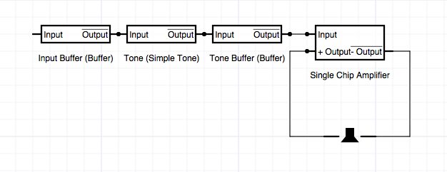
Here is the basic design:
All of this brings me to the idea of adding a simple transistor pre-amp stage before the LM386 with some sort of gain control and post volume. This may be trickier to work out than it seems, I’m still doing some research.
I did a simple test using a Mister Crybaby Super pedal before the amplifier – this pedal has a volume boost in it. I brought the amp volume down to a point where it was pretty clean sounding and then turned on the boost switch on the Crybaby. The result was a pleasing distortion from the LM386 from being overdriven. This leads me to believe that at the very least a pre-amp should be able to easily overdrive the amplifier in a nice way, assuming it’s setup right. I don’t suspect a lot of power will be needed to push the LM386 to a dirt sound, however that still leaves the matter of the post overdriven controlling.
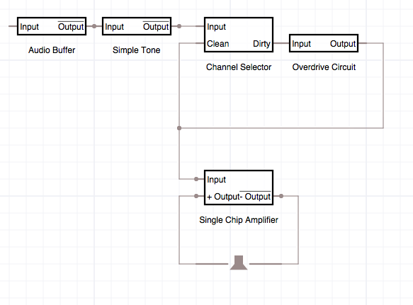
I propose that the issue of the post-gain volume increase would be probably as simple as adding a second 100k Ω log pot after the amplifier as a master. Using a DPDT switch to enable the gain would switch not only run the signal through the pre-amp, before the LM386, it would also switch the output through the post-gain volume control. This should enable the ability to achieve a levelled distortion sound.
This is a simple block diagram of the amplifier in this configuration:
By creating a pre-amp stage, distortion and a post control, this leads to another thought – something like a PT2399 IC echo unit, wired up to be a reverb could be added to the output. However, you would want that after the distortion but before the power amplifier. For that matter, any sort of delay effect would need to be placed after the signal gets distorted – otherwise the amp would be distorting on the delay effect and making a muddy mess of the sound.
It’s easy enough to come up with a simple mixer design that splits the signal off to an effects loop and then mixes the wet signal back into the dry signal – you could even add a balance pot to control that if you wanted to get really fancy – but how to get the overdrive sound and then run it through an effects loop at pedal levels and then through the LM386 when it is the LM386 that is creating the clipping naturally? I don’t think I would want to run the amp’s output levels through a pedal – that sounds like a VERY BAD IDEA.
I’ve not got a solution to that particular bit of design theory yet – my best idea so far is to run the signal through an LM386 with pre-amp or gain as described, bring the signal back down to input levels (safe for pedals) send it through the effects loop, run it through another buffer and then finally back through another LM386 amplifier to the output.
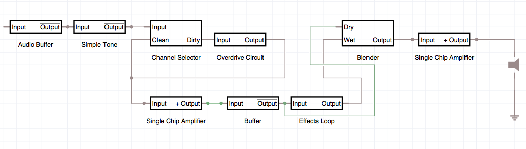
This is probably getting far more complicated than this amp needs to be, but here is a module concept for such a circuit. Note that I’ve not come up with the wiring for this craziness, it’s just a theory.
Something a bit more reasonable would probably look like this:
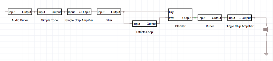
With a post volume control (engaged along with the gain channel on the LM386 via the same control switch) the first amplifier acts as a pre-amp with gain distortion. This is fairly attractive since the LM386 makes a fairly pleasing ’80s metal sound when driven at high gain.
Some sort of filter, perhaps a voltage divider, would be in place to bring the levels back down to pedal-safe and then it gets split off to the effects loop which gets mixed back with the dry signal, run through another buffer and then re-amplified for power. I have no idea if this would actually work in reality or if it would just mangle all the life out of the guitar tone.

No Responses to “Miniature Guitar Amplifier – Dual Channels and Effects Looping (Feature Creep)”
Trackbacks/Pingbacks