

A few days ago I was lamenting, in a rambling sort of way, about being unable to get the distortion channel working on my test design. After redesigning and breadboarding the circuit many times I finally came across the core issue – I was configuring the op amp in a non-inverting format which was having unexpected results with the feedback loop. Once I realized my mistake I quickly whipped up a new version.
Note that this is an approximation of the circuit, I’ve not 100% verified that this is perfect representation of what I have wired up.
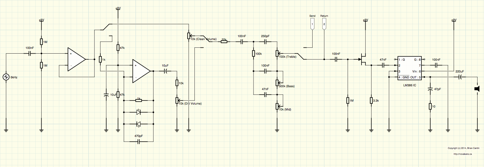
The above schematic could use some cleanup of the drawn layout, but it shows the basic idea. I am using an MC4558 dual op amp chip to handle both channels of the pre amp. There is a DPDT switch which allows switching between the two channels. The first half of the switch takes the output of the input buffer and either switches it to the clean volume control, or alternatively into the dirt stage. The other half of the switch selects between the output of the clean volume control or the dirt volume control which is then sent through the tone stack. The tone stack outputs into the effects loop which returns into a FET buffer and then goes into the power amp as per my previous designs.
This keeps the part count to a minimum due to the clean pre amp channel being simply an op amp buffer circuit. It could just as easily be done using two single op amp chips if you don’t have a dual handy. One thing that is missing from the above circuit is a gain adjustment pot. My plan is to try out a 500k and a 100k potentiometer to see which creates the best output. Additionally, the output of the 2nd channel is far too loud at this time – the 10k resistor before the dirt volume pot helps attenuate the levels but not enough. The end result is that to achieve a matching volume to the clean channel requires that the dirt volume be set far too low – so I’ll need to experiment with this some more.
One other aspect needing some tweaking is the LED clipping diodes. Thus far I’ve been using two of the same LEDs that I grabbed out of my parts bin – I want to try out a few different ones to see which produces the nicest clipping sound, ideally asymmetrically to roughly simulate a tube type distortion.

No Responses to “Miniature Guitar Amplifier – Rough Two Channel Design”
Trackbacks/Pingbacks