

The saga continues – this version of the circuit is one I am quite proud of. There is no dirt or distortion options in this design, I was going for as loud and clean as I could drive the LM386N amplifier while getting a nice rich sound.
Schematic
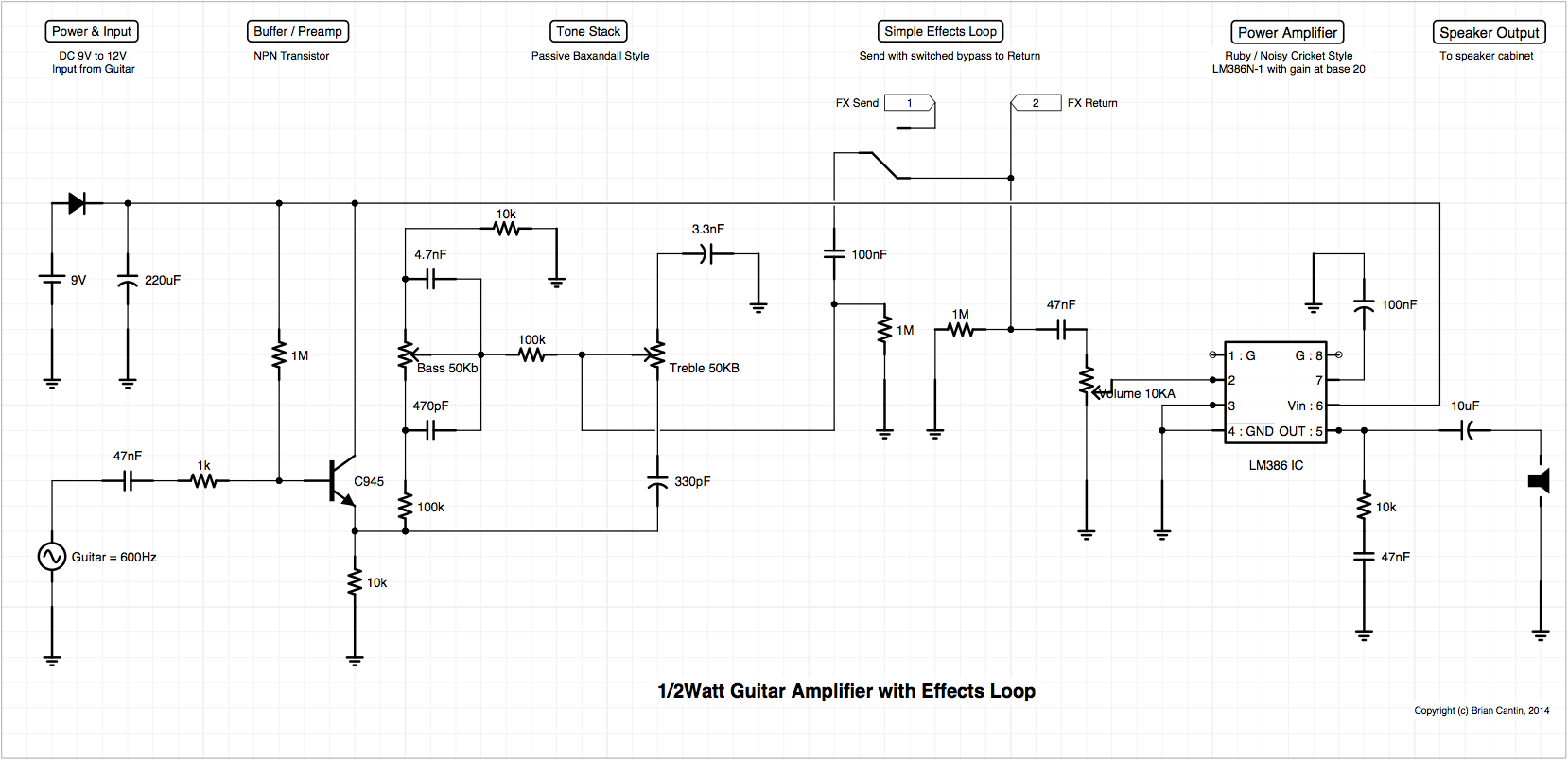
Power & Input
Pretty self explanatory. The power can be a standard 9V battery or it can be a switching jack for AC adapter 9-12V. The power switch is not shown, but it’s placement and use should be obvious.
Guitar input is a mono 1/4″ jack as you would expect. Ignore the “= 600hz” on the diagram that is just a signal I was using for testing it through the simulator.
Buffer / Preamp
I am still using the same basic buffer design as before, although I have changed some of the elements from the previous attempts. This circuit is based on the C945 NPN transistor and it boosts the signal a little bit to compensate for the two control tone stack that follows it. It also brings up the full range of the guitar signal, especially the higher frequencies which are noticeably lacking when you run a guitar direct into the power amplifier portion of the circuit.
This preamp design adds no noticeable distortion to the signal and I have tested it with the tone stack that follows and a few different effects pedals (only one-at-a-time so far) on the effects loop and it is performing as intended, near as I can tell without running it through a scope.
I did try a JFET version of the buffer, but the NTE451 FETs that I have currently are not up to the task – I have some more appropriate ones on order in a big transistor kit, but won’t be able to play with them for a few weeks. Honestly, this current buffer circuit is working so well I might not spend a lot of time working on the FET variant, it doesn’t seem necessary.
Tone Stack
This is a passive variant of the Baxandall style tone circuit, very popular in Hi-Fi and early guitar amplifiers. It is still in use on many popular amps. Except for the top end of the treble range it is fairly non-interactive with the volume of the signal compared to the tone stack I was previously using which is a nice bonus. It generates a nice mid-hump to the sound instead of just scooping out the bright shimmering tone coming out of the buffer.
Simple Effects Loop
There is not much to this – the Send jack is wired with a bypass to the return path. When a cable is inserted into the Send jack it disconnects this return path. The signal path routes externally from the amplifier to the time-based effects pedals and then back into the Return jack where it gets passed directly to the power amplifier.
The volume control going into the power amplifier portion follows the Return path immediately.
Power Amplifier
This design is well documented – at it’s core it is similar to the Ruby and Noisy Cricket amplifiers with the main exception that it’s been designed to remove all of the dirt/distortion elements from those designs. This is one clean machine!
Speaker Output
I’m running this into a seven inch 8Ω Fender speaker, built into a Squier 15 practice amplifier. I was never overly fond of the tone from that amp and I am coming to realize that the speaker is a part of the problem. It distorts and clips in the sparkly range of the high end, which requires you to either attenuate those frequencies with the tone stack, or lower the amplifier output. I spent far too long fiddling with high-pass and low-pass filters in various parts of the circuit before I realized it was the speaker that was distorting, not the preamp.
This amplifier is astoundingly nice sounding, it doesn’t really break up at all when run at full volume and that was the aim for this particular revision. I wanted a really clean setup to experiment with in order to eliminate some variables of distortion. It’s best to add any sort of dirt to the guitar sound before the effects loop and the power amplifier. For a simple test of some dirt on the amp I used a Big Muff fuzz pedal on the guitar before the input, briefly, and it handled it just fine without adding further distortion into the output.
The next task is to build a second preamp with a lot of gnarly gain and a pre-volume control that can send a nice saturated dirt sound to the power amp – the trick is making it also play well with the effects loop.

No Responses to “Miniature Guitar Amplifier – Clean Channel with Effects Loop”
Trackbacks/Pingbacks