

Following some of my previous work playing around with the LM741 op amp I came up with this alternate design for my previous clean amplifier circuit.
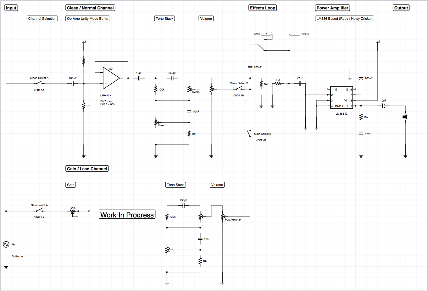
I have played with a few variations on fuzz style gain preamp circuits, but I’m still exploring the options, hence the “Work In Progress” section. One thing I learned is that the gain preamp needs to be silenced when running on the clean channel, it will still distort the signal if it has input even if it’s output is disabled. I presume this is some sort of feedback into the circuit.
To this end, my next version of a dual preamp setup will have a DPDT switch to toggle between the circuits as well as the effects loop. Although it makes little effect on the loop currently, I have a suspicion that the gain channel may need some extra trickery or at least some different value components on the Send channel when all is said and done. Regardless, this will keep the channels fully separated.
The op amp buffer / clean preamp (the LM386 has such simple needs) is louder than my previous NPN transistor buffer but I find the tone is not quite as warm. I welcome the extra headroom for the incoming signal, even with the tone stack in place the buffer is capable of creating a subtle bit of overdrive into the power amplifier stage. The single C945 transistor buffer was able to create a nice clean drive but was unable to push the amplifier to clipping – not a terrible thing, but it meant that getting a playable volume out of the design required cranking the volume all the way up.
My experience thus far is that it’s better to have a little more room and it fits in more with my overall design aesthetic I’m working towards. This design uses roughly the same number of components as the NPN buffer since the op amp is being run in unity mode with no gain. I’ve also changed the tone stack to a different model that uses fewer components.
Edit 9-Sep-2014:
Some notes about the above schematic – there is a ground connection in the RC network on the diagramed effects loop return signal – the amp will not work if this connection is there. Additionally the capacitor after the RC network following the power amplifier should be 220 not 10. There could be other errors, this is just an example schematic, your mileage may vary, I make no guarantees at this point of the project.
Another thing to note, I did try the clean channel volume before the input buffer – don’t do this, although the volume does work it sucks all of the tone out of the guitar.

No Responses to “Miniature Guitar Amplifier – Op Amp Edition”
Trackbacks/Pingbacks