

Based on my research into using op amps configured as voltage followers, otherwise known as unity gain, I’ve been testing out using one at the return point of the effects loop – this seems like a good idea so far and appears to work OK as well. The idea is the same as using a buffer at the input stage of the amplifier, to prevent loading the effects units on the loop.
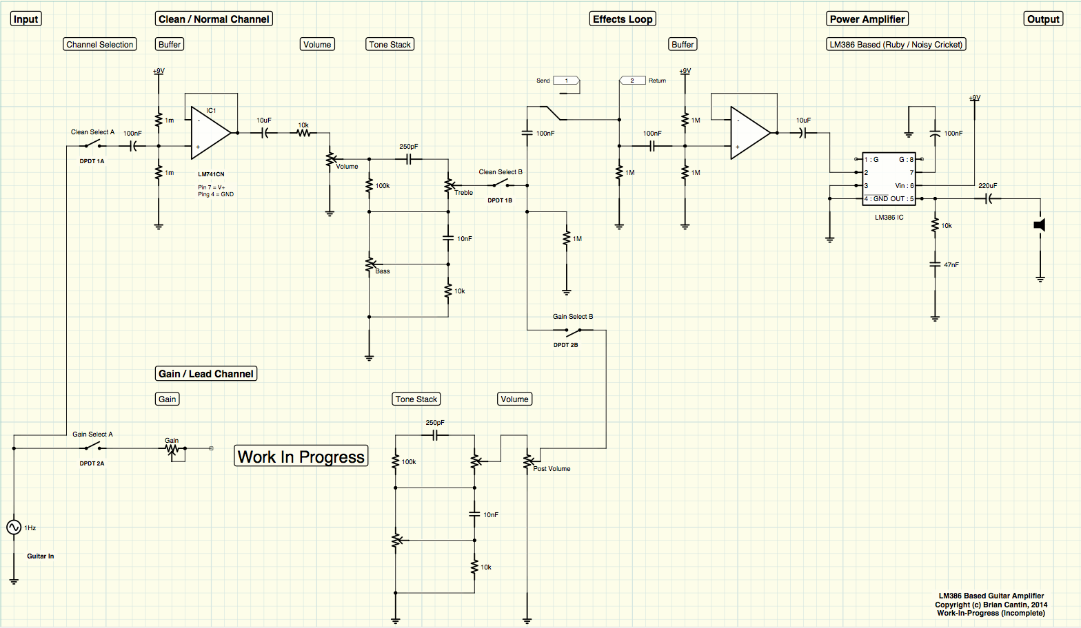
This is my test circuit as currently breadboarded. I am testing out a few modifications from my previous version of the op amp based design. I have moved the volume control to before the tone stack (which is loosely based on a Fender brownface circuit) and I have also added a 10kΩ resistor in series with the volume pot. I played around with a few different resistor values until I got the sound I was looking for. The basic idea was to limit the output volume of the input buffer so that it doesn’t overdrive the LM386 amplifier when set to full volume.
The effects return buffer should prevent loading any effects in the loop and buffer the signal prior to being amplified. I’m not sure if the 1MΩ resistor going to ground on the effect return line is actually needed since it is followed by an RC network going into the op amp, I’ll need to research this a bit more.
I have on-hand some MC4558 dual op amp chips which I have been experimenting with. Several professionally made amplifiers use such a chip in their schematics, notable to me is my Peavey Studio Pro 110 which uses a handful this exact IC, and my Fender Squier 15 which uses a different dual op amp chip in much the same way. So far I seem to be having troubles getting the circuit correctly laid out for single-supply mode, but that is entirely my fault and ignorance rather than chip – I think I should be able to accomplish it. If my understanding of the Peavey and Fender schematics are correct, they use one portion of the IC for the input buffer and the other is integrated into the tone stack.
The Squier 15 circuit actually uses a M521B op amp and implements the volume and gain within the same network which is a simple way to add distortion on the amplifier by cranking up the gain in the pre-amp stage. It uses clipping diodes on the signal after the tone stack before sending it through an NPN buffer and into the master volume which precedes the final power amplifier. It’s a very simple amplifier design and in fact that’s pretty much all there is to it: Buffer with Volume and Gain > Tone Stack > Clipping > Buffer > Master Volume > Power Amplifier.
The Studio 110 uses a more complex implementation using a separate channel for the gain. The clean channel is an op amp circuit with an integrated “Pre” volume control, much like on the Squier but without the extra gain. The lead channel has another op amp with an adjustable gain circuit followed by the clipping diodes which goes into the “Post” volume control and then a tone stack. This is followed by what appears to be another buffer circuit. Yet another 4558 op amp is used before the effects send and again on the effects return. A lot of what follows in the signal chain is circuitry to handle the amplifier’s built in spring-reverb unit. This all goes into, you guessed it, another 4558 op amp buffer before the final power amplifier stage.
I’m examining these two particular amplifiers mainly because they are the two solid-state amps that I own, so I am familiar with the effects of the various controls and can thus better understand the nature of the circuit functions. The Fender amplifier is extremely simple in it’s design – it would be very easy to recreate it’s functionality in a low-wattage LM386 amplifier. One of the downsides to the design is that gain is only controllable through the potentiometer control (no toggle switch) and the volume/gain/master sequence is highly interactive. This means you spend an inordinate amount of time fiddling the nobs to get the sound you want at the volume you want, and any change in gain will set you back to fiddling with the volume and master again. It also has no effects loop, so studying it’s design won’t help me there. The distortion when the gain is cranked however is actually not too bad sounding for what it is, so that portion of the circuit may be interesting when I get back to working on my own “lead” channel circuit.
The Peavey amplifier is a much more complex device and I’m still struggling my way through understanding how it does what it does. The effects loop works particularly well, and it’s use of op amps that I happen to have on hand has renewed my interest in trying to get one of those chips to work. I’ve also glanced over the schematic for the early Peavey Bandit amplifiers since they seem a bit more straight forward in their layouts, however they use transistors more so than op amps.
I’d like to try to improve my design by integrating some dual op amp chips into the circuit instead of adding a whole whack load of single amp chips to get the signal at proper impedance levels for the effects loop.
